Wednesday, August 24, 2011

1955 Chevy Radio

Another R/R sucess? A project completed? How can that be?
The radio is now back in the hands of its owner!  I hope it works in the car as well as it did on the bench.  After adding the new Potentiometer, and the final tweaking and getting the shields in place ~ It worked great.  All the daytime stations were tunable, no more noise gap in the tuning range.  It sounds OK...

The one issue I found was in the new the variable resistor/volume control.  The switch and the main control seemed to work OK but the control seemed "loose" to me. When it was soldered in place, my suspicions were confirmed, the control was noisy, the wiper of the second resistor is not very tight. 

I pondered what to do about this and accidentally came up with a solution that worked great.. The second resistor (R51A) is not the volume control per se, but sets an AC ground path thru C22:

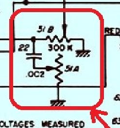
It looked like the problem was the bounce of the wiper was causing the noise, that is it went to infinite resistance temporarily and then when it reconnected with the resistance caused the noise.  So as an experiment, I wanted to see if I could bypass the resistor so C22 always would have at least some contact at all times.  I placed a 100k resistance between the wiper and ground and it cleared the issue up 100% !  It worked so well I left my test resistor in place and never heard the issue again.  Since the resistance is so large a 1/4W resistor was fine and fits nicely between the terminals.

 The original in place...

Control  Assy was pulled from another radio,  we were not sure they would work but the values were same even though it was from a differnt model year.

 Some damage on the original may explain the lack of switch control, the terminal board is cracked and this smay have caused the cam to slip off the switch control. 

I'll put some pics up later of the radio in the car after it gets installed.

Monday, August 15, 2011

1955 Chevy Radio


Here is another sample of the audio during operation, between the channels you can hear the noise created by the high voltage supply. 


Here are some of the caps I replaced work in progress. The orange drop caps were in place of some of the wax & paper foil caps pointed out in the last post.  The blue electrolytic is in place for part of the large multi cap which I left in place but removed the leads and routed the compnent leads to the points in the circuits. There are a couple more caps that need to be replaced see in lower left of this view.


1955 Chevy Radio


Here is a sample of the audio, the buzzing sound is the mechanical vibrator / chopper in the high voltage power supply which supplies several hundred volts DC to the plates of the tubes:


Saturday, August 6, 2011

1955 Chevy Radio

The radio repair was quite straight forward, the major problem was one shorted capacitor in the power supply.  I replaced all the paper and electrolytic capacitors with modern Tantalum and Mylar caps.  The other major issue was the switch.  The switch was stuck in the ON position. Which allowed the testing of the radio.


I was quite pleased that the tubes and vibrator worked.  I connected a 13.8V Power supply, speaker and antenna. 

The first station it tuned in was ~  appropriately enough ~ the KFSD AM 1450  "oldies" station in Escondido, CA.  I also was able to tune in the local San Diego talk radio stations as well as Tijuana, BC stations.  The sensitivity was not the greatest but a half a dozen stations could be clearly heard. 

The vibrator buzz can be heard between stations until the AGC takes over on a strong signal.  The selectivity was OK.

As the night time clear channel broadcasters came on many more stations including 640 KFI (Los Angeles) , 680 KNBR + 810 KGO (San Fransisco) and 1160 KSL (Salt Lake City) and XEPRS (Rosarito, Mexico) were all heard.

There seems to be a peak of the vibrator's noise in the upper center of the band, but 680-550kHz stations are heard again with some quieting as the AGC takes over.  It may be my antenna or there is a bypass capacitor not working or soldered correctly.

Besides the shorted capacitor, most of these were simply out of tolerance, or had a significant value change over the last 5 decades!  For example; the 0.002uF was reading 0.008uF  ~ it still was working as these are not used for any critical frequency determining elements, but this tells me there are changes going on to the old paper, wax, and foil and it is only a matter of time that they would fail...