Monday, March 28, 2011

CBAND Scan

The old C-BAND has been sitting on the NASA channel AMC 3 W3 87°West  

This weekend I decided to do a couple of scans, on nearby satellites the NASA Channels still on AMC 3 (W3) They also have a HD channel, I may have to get an HD receiver...I wonder if a digital TV adaptor will work?  I need to figure out how to get an RF output.

4.000,
15, H
DVB 
  28111
3/4 
 
4.000,
15, H
DVB 
  28111
3/4 101
273
  276
4.000,
15, H
DVB 
  28111
3/4 102
289
  292
4.000,
15, H
DVB 
  28111
3/4 103
4145
  4148
4.000,
15, H
DVB 
  28111
3/4 104
4161
  4168
4.000,
15, H
MPEG-2/HD 
  28111
3/4 105
82
  83, 283
Other interesting stuff on Galaxy 19 (GB) 97°West and  NGC,  FOX Classics Movies, and FOX news were coming in Unscrambled on the digital FTA receiver.  

The old sat sites are of course way out of date! I am amazed this old thing still gets some useful channels.

http://channel.nationalgeographic.com/ngcweb/xmlFeed/printable.jsp?timezone=pt&week=2

http://www.foxmoviechannel.com/schedule.php

Wednesday, March 23, 2011

MK-III ~ Crystal Holders


~~1930s Ham Radio Transmitting Crystals~~

Yesterday a matching pair of “no-name” crystal holders arrived  par avion from the Great White North

These are Bliley style Round holders, Pin diameters are 3/16” with ¾” spacing, but were probably sold through Leeds Radio. 


For an excellent history of the Bliley company see: http://www.bliley.net/XTAL/


 They look awesome on their new home; the Mk-III prototype! ...and the RCA sockets work great on these pins as well.

The mechanics of these holders is very interesting, and very well made. One pin is connected by a spring in the bottom center, and the cover to the other pin marked "GND".  On a quick glance it is not apparent how they are even electrically connected!  I think these holders were meant to be for experimental or lab work, which is probably why they were never labeled;  they are easy to assemble and slip in a new crystal and looks like they are good for many open/close cycles.  

I have to figure out how to get new crystal elements in these, the HC-49 crystals I used in PARASET may not work without re-working, and I think I want to keep them intact.  One has an element that oscillates at 3935 kc I may simply get some new actual crystals, I think I saw a ham who will custom grind these!  

I can always use the PARASET crystals as well for On-air but it would be cool to have a couple in theses holders as well, especially a 160M QRP  - which I do not have.

~ ~ ~

PANEL UPDATE:

After studying the pictures again and another ca. 1940's period spy set (Mk-XV); we added and moved some text to the engravings on the panel:


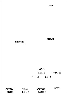
The Meter looked as if it was for the crystal, so I moved the label,  I have a screw mounting in the center of the crystal's pins so I moved the "CRYSTAL" label below the holder and I also noticed that the bulbs are always labeled so I added "OSC INDIC"   ~ ~ OK The call sign is a vanity thing I guess, but it will be covered up by the Ser No. Plate anyway!

~ ~ ~

Monday, March 14, 2011

MK-III ~ Panel Prototype

I got the first prototype panel today done by Bert in his garage shop this weekend. 


Bert’s homemade CAM machine seems to be working OK.  There are a number of adjustments to make but the results are way better than the early one I made by hand.


The fiber board we used is actually Art hardboard panels.  Since I designed my version of the MK-III to be 5” x 7” the exact size board can be found in art stores:  Art Supply Warehouse


BTW - If anyone else ever wants to try the VKF MK-III version we can now supply panels ~The setup alone for would have cost me a fortune,  but this was very economical as we supplied our own labor!  ( ...and a few broken milling parts and raw material.)

Tuesday, March 8, 2011

Mk-III

Progress on the Mk-III panel. My version is a combination of the SCU09 and the “Coffin” set photos from the Bletchley Park museum:  


The panel layout I used is being fabricated to test out a home made CAM machine.  But here are the results of the first proto layout from this weekend in the shop:


Mk-III Panel - test fit

There are a few minor adjustments need to be made; First the counter sinks were too deep for #4 hardware, but that was just operator error  - I forgot to reset the drill press depth screw from the #6 holes.   Secondly, the bottom screw on the panel to the lower left of the bottom dial - which is  intended to be a ground tie point for the "Aerial" capacitor to the panel shield -is much too close to the chassis to fit a nut and solder lug is just a simple adjustment to the drawing.  

Mk-III Panel Proto with Finish


The only other issue we are running into is the letters, in order to use white lettering we intend to use the CAM machine to engrave the letters and I will fill with white paint.

Mk-III Lettering

These need to be “kerned” or spaced a little to allow for the thickness of the tool.  The other issue is the “Futura” font used is not available on the CAM software and it seems to be drawing outlines which makes for a thick letters, so we can not use the lettering feature.  But with a .DXF file the font does not matter, it is all just lines and curves.


Here is the result with  a DXF file.  It is only a test panel with some OSB material, and the engraving is filled with drywall mud to test ...but it looks like a very good start!

Thursday, March 3, 2011

PROJECT:3.1415926535897932384626433832795


Steve's Pumpkin Pie Recipe

~~~


So we occasionally get hungry down here on the radio ranch, and like all my projects you can just go and buy one.  But what fun would that be?


 This one was handcrafted at that strange time of year last November, seems like it was on the third Thursday it was...

The main ingredients are:
 

Shockingly delicious?  We’ll see about that:
 
(basically we  followed the cooking time on that little green label)

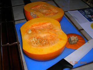
Dismantling the gourd.
 
Real "Artsey~fartsey"?


Seedy huh?  (These also baked up and tasted so good! – Rinse, dry, lay out on a cookie sheet, little kosher salt, THEN bake on LOW, residual heat from the pie I think,  for a bit until  toasty done ...and tasty good)


Out of the oven, baked covered with foil in a shallow pan with some H20 until tender..as directed.


Mashey mashey.   We do not like pumpkin custard pie, and stringy is out of the question so this part is critical!


“..I’m hungry; can I help eat it now?”
 

The crust was homemade...of course.
(Wheat flour,  Fat, more fat, H20 {some was below 32°F and some was liquid state},  and a few sodium chloride crystals , blended ~skillfully~ with my pastery thingey..


Basically the rest of the formulae!  (The exact proportions are of course: CLASSIFIED)


Out of the oven!  Slightly baked the crust first with a second pan on top to keep the shape. (An old baker’s secret I got from reading a cookbook! )


If the shoe cuts it ..eat it.  (A well healed pie server huh?)
 

You have been... Well Served!


...OK  you were expecting a traditional PUMPKIN PIE recipe from Steve?  This pie was so fookin "darned-good" I think you have all the info you need now go fourth and bake one!

Tuesday, March 1, 2011

That's Just a ReCAP!

Here is a some documentation I made when I rebuilt a multi-cap for my Halicrafter's S-120 Radio** repair I did in October 2010, it was a 60-40-40-20, my stack was 68-47-47-22 of equivalent or greater voltage ratings of the original.


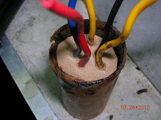
The cause of much power supply noise:


Wax holds it together:


Heat takes it apart:


Capsule removed:


* It took a bit more heat than imagined, this brown wax is really very hard stuff, some flowed out as planned but I could not heat all sides so it was stuck firm.  I ended up using some leather gloves and pliers to help hold and pull out the old foil caps while evenly heating the paper tube with the hot air gun. 

 A new "CAPsule" fabricated, It was a bit of a stack to fit all the new caps:


Fits OK:

Added a cardboard spacer for two reasons; to create a void space for the safety vents on the new caps, and to have the same wires and lead pattern as original, but it ended up in a slightly different order to match the new stack with no internal crossovers:


Completed new capsule, added a little more kapton tape some hot melt to prevent wax dripping in and closing up the cap's vents:


Ready to re-melt the wax:


Done:


I did not get a photo in the radio but it looks original, I marked the cap as a re-work, as shown. Although the lead layout was very logical for my stack, ground was in the center but I wish I would have paid attention to the original order because one of the yellow wires was a little shy from its new location and I had to splce a short piece of wire on it; but thanks to some yellow heatsrink it is hidden for a casual observer. 

**This S-120 is no real historic radio or anything,  just a 1960's cold war era tube radio ~ the significance to me is this is the first short wave radio I ever owned, and still have it. The original re-cap was done in September 2010, and I replaced all the paper and "bumblebee" caps, along with simply cutting these leads leaving the multi cap non-functional by adding new electrolytics point-to-point. I replaced those electolytics with the multicap I built with this re-work. 

I have been listening to some shortwave on this radio again  in my lab but am not sure some of the stuff I hear on the bands these days is any better than the government run jammers we heard on it back in the '60s.