The 2002 Dodge Ram 2500 Diesel Get NEW Headlamps!
THE BAD:
OK so it was 3 mo. since the Escape got its new eyes. We have not been idle at the radio ranch either... After one false start from a stupid company (who shall remain nameless). It is a shame, because they were fast ship and had better Tyco parts...
Update: 5/6: OK, the first company is in contact with me so we may be able to get the restock fee issue worked out! Well then, I still need new fog lites... hint hint ;-)
As it turns out; the Dodge Ram 2500 changed the mounting details of the headlights in 2002. I am (un)lucky enough to have the transition model year! The further complication of "Sport" or "non-Sport" packages. Anyway, as we say down on the Rancho Radio; live and learn, I guess some folks are happy sending the wrong parts and then collecting a 12% restock fee even after their parts match says "perfect match!" I can totally see if I order wrong model year parts or just don't like the looks. OK charge away, but If that is the way they want to do business then fine. I will take mine elsewhere; 'nuff said.
So... if you have a 2002 Dodge Ram P/U just be careful; it looks like the ones that fit 1994 - 2002 models could fit your particular mounting, especially if you have an early 2002 then it may NOT be able use the 2002 - 2005 headlights. It is hard to tell when and with what exact production models Dodge rolled in the new mounting. So just take look at the your headlamp assy's and compare to the pictures before you order.
THE GOOD:
The guys I got these from are actually on e-bay this time (vs. Amazon) HeadlightsDepot The set I got is really a "Sport conversion" which changes the non-sport package to the cleaner one-piece sport look. It was listed as "Buy it Now" item number: 380330840315.
 They also come with these harness assemblies (more on these later):
THE UGLY:
Yes folks, this is the high beams!
Yeah, its time! There may be a slight hazing?
Yes, the light is ON! This all I see in daylight..pretty pathetic!
DO IT:
Complete kit arrives OK and on time by Fed Ex! (whatever happened to UPS or USPS?) It took a while to arrive thanks to the distance (cost-to-cost) and a few storms along the way. But they got here on Saturday. Now on to removal and install!
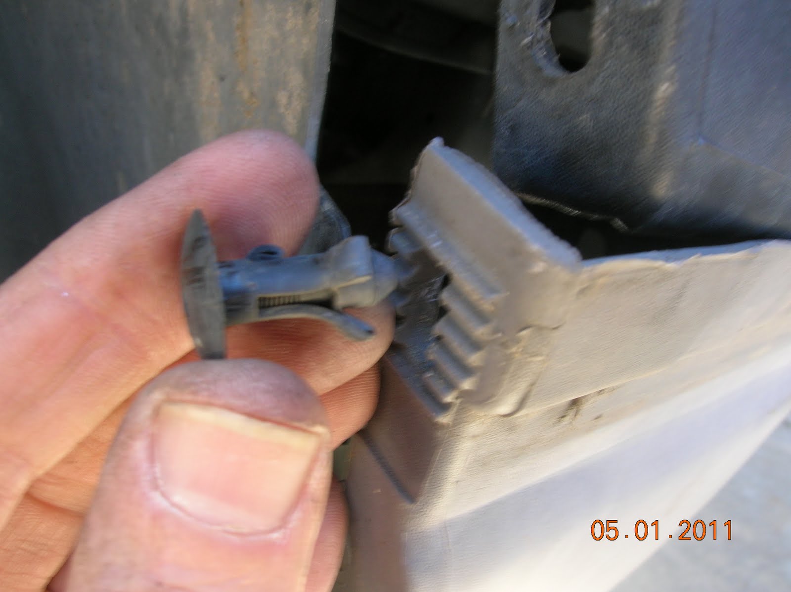
The little plastic buttons which hold the rubber gasket need to be removed. I had to pry them up a little with a large screwdriver then pulled them out with the needle nose pliers.
.
Same with the trim fasteners. You may want to pick up a couple of these plastic bumper trim holders. I think most auto parts stores have them. It really helps to get the plastic trim out of the way first.
I also loosened the torx screws on the bottom but this proved to be unnecessary.
Three 3/8" (10mm) cap bolts hold the lamp holders in place. You need a series of extenders to reach these.
The one inside the engine compartment is a bit tight. This is the one I tried to move the lower trim to get a better view of, you can reach it with a small extender on the socket. You only get a partial turn on it at that.
Mercifully, these only take a few turns to loosen...
Finally, the last bolt requires a longer extension to reach it...
The parking bulb twists out and unplug the harness on the main bulb by carefully prying the little plastic tabs and before they know what hit them...
...Done! Yeah, see the light hazing I was complaining about?
OK a word about the quality...
These assemblies are not as nice as the Eagle Eye replacements I put on the Escape. They are definitely knock offs. They were shipped, well packed but only poly bags, not the nice protective cling wrap the others had. The harness wire cables assemblies are not so neatly taped together with electrical tape. Heatshrink would have been more professional, and the spice jobs on the connectors leave a little to be desired...I don't really like to see wire exposed. but they were only $169.95 with FREE shipping...so what can I say?
There is a method I found to insert the assemblies...first start in towards the center as shown:
They also come with these harness assemblies (more on these later):
THE UGLY:
Yes folks, this is the high beams!
Yeah, its time! There may be a slight hazing?
Yes, the light is ON! This all I see in daylight..pretty pathetic!
DO IT:
Complete kit arrives OK and on time by Fed Ex! (whatever happened to UPS or USPS?) It took a while to arrive thanks to the distance (cost-to-cost) and a few storms along the way. But they got here on Saturday. Now on to removal and install!
The little plastic buttons which hold the rubber gasket need to be removed. I had to pry them up a little with a large screwdriver then pulled them out with the needle nose pliers.
.
Same with the trim fasteners. You may want to pick up a couple of these plastic bumper trim holders. I think most auto parts stores have them. It really helps to get the plastic trim out of the way first.
I also loosened the torx screws on the bottom but this proved to be unnecessary.
Three 3/8" (10mm) cap bolts hold the lamp holders in place. You need a series of extenders to reach these.
The one inside the engine compartment is a bit tight. This is the one I tried to move the lower trim to get a better view of, you can reach it with a small extender on the socket. You only get a partial turn on it at that.
Mercifully, these only take a few turns to loosen...
Finally, the last bolt requires a longer extension to reach it...
The parking bulb twists out and unplug the harness on the main bulb by carefully prying the little plastic tabs and before they know what hit them...
...Done! Yeah, see the light hazing I was complaining about?
OK a word about the quality...
These assemblies are not as nice as the Eagle Eye replacements I put on the Escape. They are definitely knock offs. They were shipped, well packed but only poly bags, not the nice protective cling wrap the others had. The harness wire cables assemblies are not so neatly taped together with electrical tape. Heatshrink would have been more professional, and the spice jobs on the connectors leave a little to be desired...I don't really like to see wire exposed. but they were only $169.95 with FREE shipping...so what can I say?
There is a method I found to insert the assemblies...first start in towards the center as shown:

Then slip the assembly to the fender side....attach the parking lamp (twists in place) and attach the harness. Reinstall the three bolts and...
COMPLETE!
Moving the plastic out of the way really helps, and I am not sure if you can install without loosening it.
Now, I need to try them after dark and do any alignment. ( I did place some blue painter's tape on the garage door centered in the old beams, but it was too bright when I finished to see even the new lights to see if they needed adjustments)
Not too shabby!
Here is really all the tools you need. It really helps to move the bumper trim out of the way so be prepared for those plastic nut thingies.
BTW: You will need a TORX driver to adjust the alignment. I marked the original centers of the beams with some blue painter's tape on my garage door of the old lamps prior to removal - this needs to be done after dark or in subdued light.
WIRING HARNESS:
The harness plugs into the existing plug socket. I had to scratch my head to decide which bulb was intended for which circuit! There is plenty of slack on both connectors ~ so that is not a clue either. Anyway, the bottom line is it looks like the bulb in front of the smaller (upper) part of the reflector is intended to be the HI BEAM and the bulb in front of the main reflector is intended to be the LOW Beam or normal driving light.
You can see the three circuits; HIGH (blue) , LOW (White) and two GND (Black) wires. But with the poor quality of workmanship, I would not rely on the wire colors alone either. You'll know and if you use the wrong connectors it is totally fooked up! You get a dim light out of the top bulb and a bright one on the lower bulb!
It looks like they intended to mark the sockets but forgot the labels on the headlamp assemblies, at least me or my helper** never found any corresponding 9004 / 9007 circuits labeled on the headlight assemblies.
But that does not matter anyway because the thing about these harnesses (IMO): they are not wired correctly! I see what they were doing, I guess it is OK. But there are now two halogen bulbs in the new assemblies, which is cool. One is operated by the light switch and the other is connected to the BRIGHT switch.
 |
As wired --
Note: they grounded the center pin on the second connector but it shouldnot make any difference as long as the circuit is only connected to half of the filiments... |
That'll be bright alright! ...but the reflector on the upper bulb seems aimed high so it may not be good for normal driving.
2) The second option would be to connect only the BRIGHT circuit to one of the filaments on the HI bulb, this way the upper reflector is illuminated, as well as the original bright filaments will come on, in this way I can control the brightness of the second bulb.
Connector on RT is the high beam
Of course, that means locating some of these connectors and/or pins! That may turn out to be more cost as much as the assemblies...I suspect the connectors (new) are in the $20 range.
The way I may do it is to simply splice the second connector for the high beam into the existing plugs...
That way the lower bulb is on both HI/LOW and the upper bulb then turns on also when HI beam is on!
It is an easy install for the second option, just cut out one of the connectors and splice it in, but using the pins from one plug to add the third circuits for the first option may work as well by splicing all three in. That way both bulbs are always on either HI or LOW settings ( If I can remove two of the pins from the other housings --they usually have a special tool to do this but they look like they will come out with a small screwdriver by pushing a tab on the pin) Anyway - we will update this story when we get one working!
~ ~ ~
**Hardly anything for my helper to do but watch out for bunnies and lizards on a sunny Sunday *Mayday* morning!
Yup, none bothered me at all..
~ ~ ~


